22857 Analysis of turbulence-induced vibration in a square-lattice tube array
Begeleider(s): dr. ir. Henri Dolfen

Richtingen: Master of Science in Electromechanical Engineering

Probleemstelling:

Nuclear reactor cores in Pressurized Water Reactors (PWR) are composed of an array of cylinders (i.e. the fuel rods) placed in a pressure vessel (see Figure 1). During normal operation, water is pumped at high pressure through the fuel rod bundle to evacuate the heat. As a result, the cylinders are subjected to an external, axial flow which causes the cylinders to vibrate. Vibrations due to axial flow have not been investigated as thoroughly as cross-flow, even though they provoke long-term damage such as fretting and fatigue. Fretting damage is one of the main causes of for nuclear fuel leakage which costs power utilities millions of euros. Beside nuclear reactor cores, tube bundle geometries subjected to external flow are also often encountered in heat exchangers, in particular in the shell-and-tube type. This makes this case relevant to more industries than only nuclear power generation. 

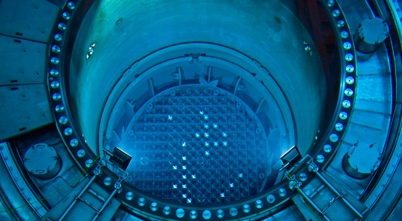
Figure 1: Picture of an opened PWR reactor core.

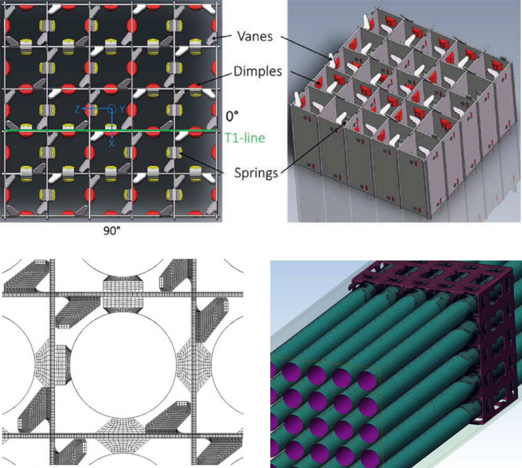
In order to mitigate the most severe vibrations and preserve the distance between the fuel pins, the rods are placed in spacer grids. These spacer grids often have mixing vanes, introducing swirl to the flow which enhances heat transfer (see Figure 2). The spacer grids result in an increase of the turbulence intensity downstream. It is of interest to know how this turbulence evolves over the axial length because this has implications for both the heat transfer and flow-induced vibrations (FIV).

Experimental work on these tube bundle geometries exists, but experiments are expensive and the geometry might prevent access to certain locations.  With the rise of computational power the last decades, the predictive capabilities of numerical simulations became available. Computational Fluid Dynamics could prove a valuable complement or alternative to experimental work, yielding detailed information on the flow-field at all locations and helping in a fundamental understanding of the flow phenomena.

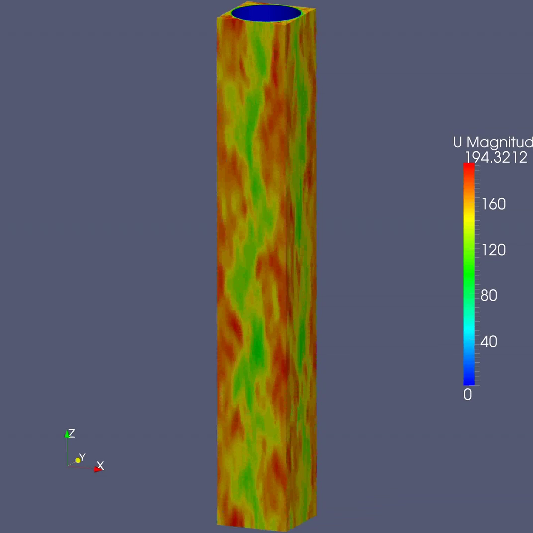
In this case large eddy simulations (LES), in which all turbulence besides the very small scales is resolved and only the latter is modelled, are considered to study the effect on the flow of the spacer grid of a PWR fuel bundle. In particular it would be interesting to know how the turbulent velocities and pressures evolve in downstream direction and estimate the impact on flow-induced vibrations by applying the forces to a structural model (finite elements). The results can be compared to experimental work and other numerical research and add a valuable contribution to the understanding of the thermal hydraulics of fuel assemblies.

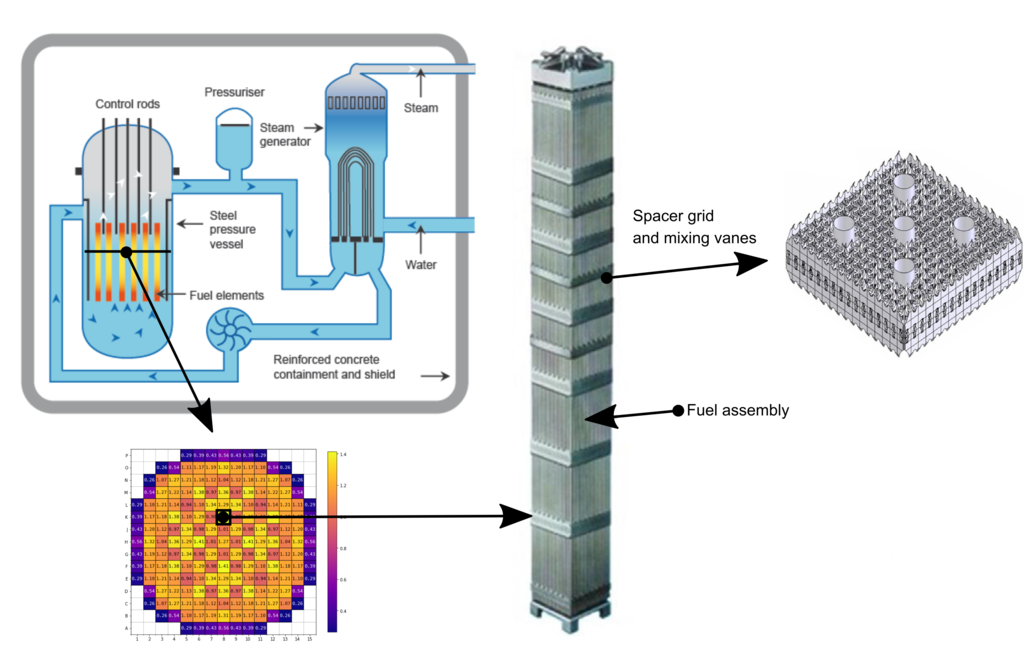
Figure 2: Overview of a PWR reactor and a typical fuel assembly.


Doelstelling:

The first step of this thesis will be dedicated to constructing a simple CFD model of the tube bundle, for which we can rely on experience from previous research, performed by thesis students and researchers of our group (Figure 3). From this already some useful information will be won about the turbulence properties in the developed flow. In this first step the computational demand will be evaluated and it will be decided which resources are required and what size of mesh is feasible. A performant, multi-core computation server will be available, and the High Performance Computer of the university will be used. 

Figure 3: Large eddy simulations on a single cylinder. (Also see https://www.ugent.be/ea/eemmecs/en/research/stfes/flow/gallery/cylinder.htm.)

Depending on the first step it will be decided to continue the research on a 5 x 5 rod bundle, a 3 x 3 rod bundle or a smallest representative periodic unit, which is a single cylinder that represents a larger bundle using periodic boundary conditions. The CFD model will be extended to include the spacer grid (and eventually mixing vanes). The mesh generation of the spacer grid is novel and will require some creativity which can be inspired by examples found in literature (some are shown in Figure 4). As a compromise will need to be found between obtaining a realistic representation of the geometry and keeping the time spent on meshing feasible, simplifications will be unavoidable.

Figure 4: Literature example of a mesh of a geometry.

Once the realistic model is established, simulations will run for some time, during which the post-processing can already be prepared. This will mainly happen via Python-scripts, of which already some examples are available from previous work. The analysis can happen on a more fundamental level, by post-processing the result in the frequency domain and investigating the correlations present in the flow and gaining understanding of the nature of the turbulence in a more fundamental way. The analysis of flow-induced vibrations can in that case also be derived in the frequency domain. Alternatively, an approach could be taken from a more practical viewpoint and remaining in the time-domain. In that case the pressure field acting on the cylinders can be captured and applied to a finite element structural model, yielding the structural response in the time domain and allowing a more intuitive analysis. In this case it is also possible to gain understanding in the contact between the fuel rods and spacer grids, which is valuable to assess grid-to-rod fretting damage.

In short, you will: