Probleemstelling:
Turbulence Induced Vibrations (TIV) in a nuclear reactor is an undesirable side effect of achieving high coolant flow rates. The turbulent pressure field of these flows forces structures within the reactor to vibrate. High amplitude vibrations of the fuel rods and heat exchanger tubes can lead to structural damage and create a safety hazard, see Figure 1 for some examples. TIV is a difficult phenomenon to predict and limited experimental data is available. Therefore, the most pragmatic method of determining vibrational behavior of the reactor is through a computational approach. Fluid-Structure Interaction (FSI) problems like these can be tackled by coupling of CFD (Computational Fluid Dynamics) and CSM (Computational Structural Mechanics) solvers. To simulate TIV, it is necessary to capture the turbulent eddies by resolving the fluid flow field up to the smallest scales. Use of high-fidelity CFD methods such as large eddy simulation (LES) is an ideal approach. However, this modeling approach is very expensive, especially when an FSI simulation of an industrial application is considered. Low-fidelity models such as URANS (Unsteady Reynolds Averaged Navier-Stokes) only simulate the largest turbulent flow structures and are incapable of capturing the fluctuations at the smaller scales, resulting in an inadequate approach for TIV.
![Figure 1: The left picture shows the broken in-core instrumental (ICI) nozzles from the heat exchanger. The picture in the right shows the missing ICI tubes from the bottom of the pressure vessel [Païdoussis, 2006].](/masterproef/figuren/hdolfen/damage.png)
Figure 1: The left picture shows the broken in-core instrumental (ICI) nozzles from the heat exchanger. The picture in the right shows the missing ICI tubes from the bottom of the pressure vessel [Païdoussis, 2006].
To overcome these challenges, the use of a Pressure Fluctuation Model (PFM) for FSI simulations is proposed. This novel technique allows to estimate the pressure fluctuations based on local turbulence quantities that can be predicted by URANS. In the proposed methodology, standard URANS models are complemented with the PFM to determine the instantaneous pressure that acts as a source of external excitation for the structure in an FSI simulation. One research question addressed in the thesis is how well the PFM in combination with URANS is able to predict the structural vibrations. Preliminary tests have shown some good results, see Figure 1, but much more extensive testing and validation is needed. If it works successfully, it can greatly contribute to the design of complex and important components of a nuclear reactor, such as heat-exchangers and nuclear fuel assemblies.
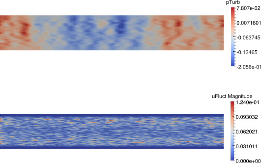
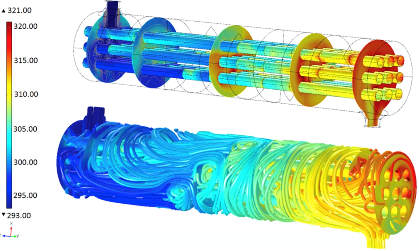
Figure 2: Pressure fluctuations (top) and velocity fluctuations (bottom) resulting from the Pressure Fluctuation Model.