Probleemstelling:
The wet clutches in hydrodynamic transmissions (Figure 1) and e-transmissions (Figure 2) are used to select the vehicle driving direction, the requested gear ratio or the optimal mode. As such, a typical DANA hydrodynamic transmission contains 2 to 8 wet clutches, and e-transmission contains 2 to 4 wet clutches.
Typical applications of these transmissions are shown in Figure 3. To reach a continuous wheel torque during a shift sequence in these heavy machines, one clutch is opening while another clutch is closing. Hence, both clutches are slipping, which induces power loss and generates heat in the clutches, depending on the time of overlap, the gear ratio to be realized and the vehicle and driveline inertias. Typical power paths are shown in Figure 4.
Figure 5 provides a section view of a typical wet clutch. The main parts are the separator plates connected to the drum and the friction plates connected to the hub. By applying hydraulic pressure on the piston, the friction in the clutch pack is increased and torque is transmitted from drum to hub or in the opposite direction.
Remark that the friction plates contain a groove pattern which allow lubrication oil to enter the clutch pack and cool the steel separator plates during the heat generation. In case of no lubrication, as for dry clutches, the heat capacity and the maximum temperature of the steel separator plates limit the slip energy. Thanks to the oil cooling, the slip energy can be higher for wet clutches. As shown in Figure 5 the lubrication oil enters the clutch via a channel in the shaft, but before entering the clutch pack the oil reaches atmospheric pressure around the hub. Consequently, the actual oil flow through the clutch pack is determined by the pumping effect of the rotating channels, created by the friction plate groove pattern. In case the pattern can take in less oil than provided, the lubrication is less efficient. On the other hand, in case the pattern can take in more oil than provided, air from around the hub will enter the pattern and start reducing the cooling power.
Next to the nominal friction plate flow, also the convection coefficient between the oil in the pattern and the separator plate is determined by the pattern geometry. The cooling power depends on the nominal flow rate as well as on the convection coefficient. Note that during the transmission life the friction material will wear, reducing the groove depth. It is important that the cooling power remains sufficiently high during the whole transmission life. A second aim of the friction plate design is to reduce the drag of the clutch in open condition. Again, the pump effect of the friction plate grooves is a dominant loss source. The best friction plate design will be a compromise between a high cooling power and a low drag loss.
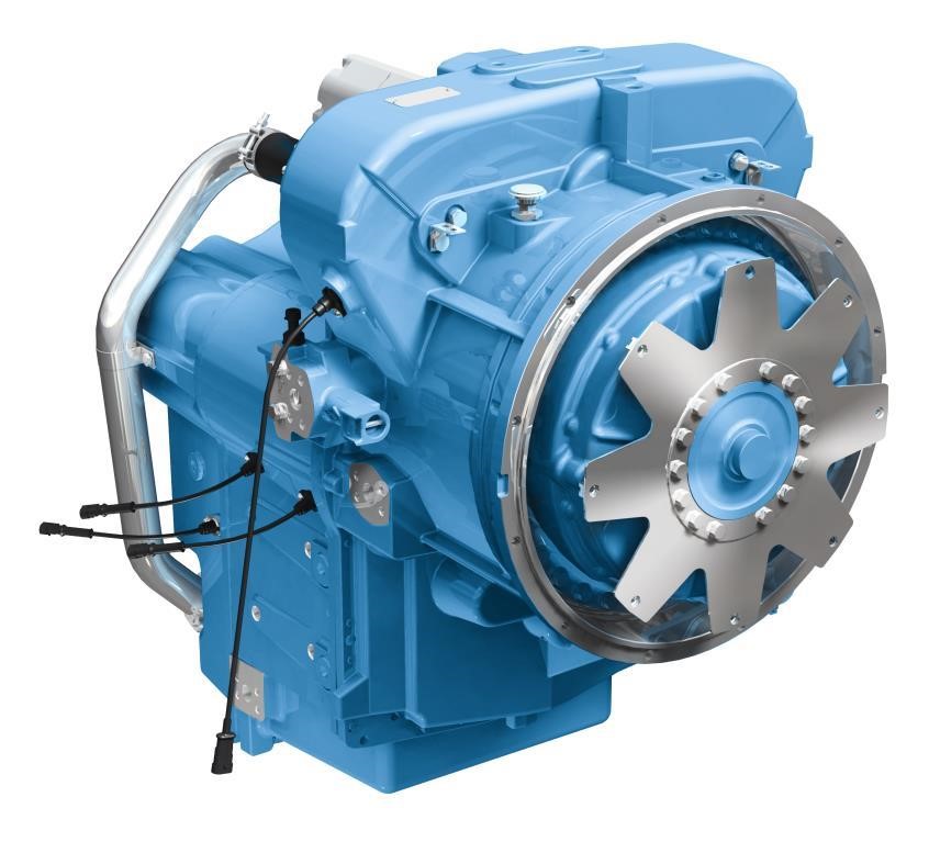
Figure 1: A powershift transmission produced by Dana Bruges.
![]()
Figure 2: An e-transmission produced by Dana Bruges.
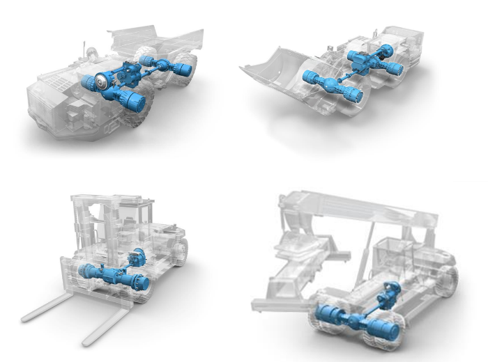
Figure 3: Typical applications of powershift transmissions.
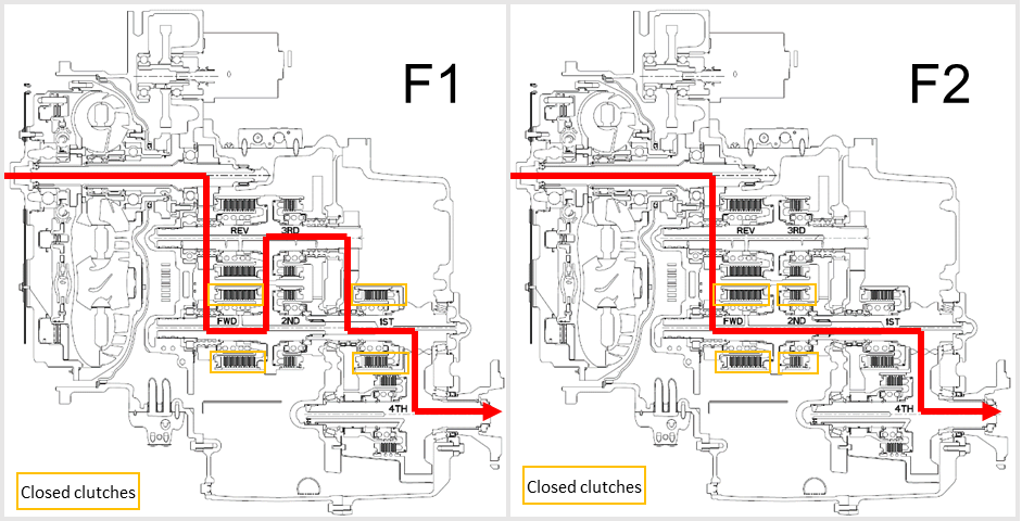
Figure 4: Power paths through a hydrodynamic transmission in first and second gear.
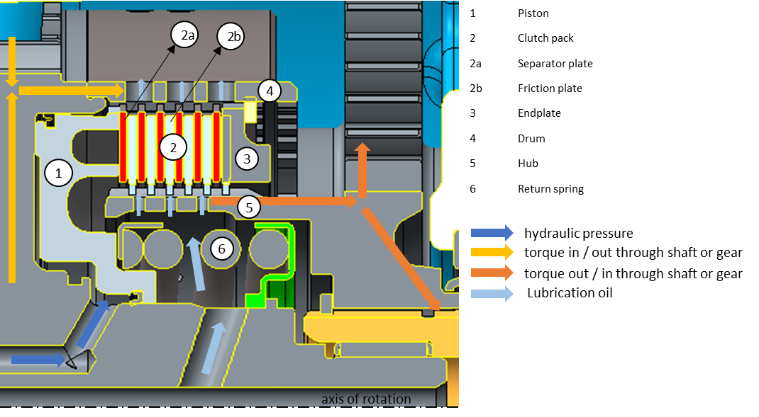
Figure 5: Section view of a wet clutch