Probleemstelling:
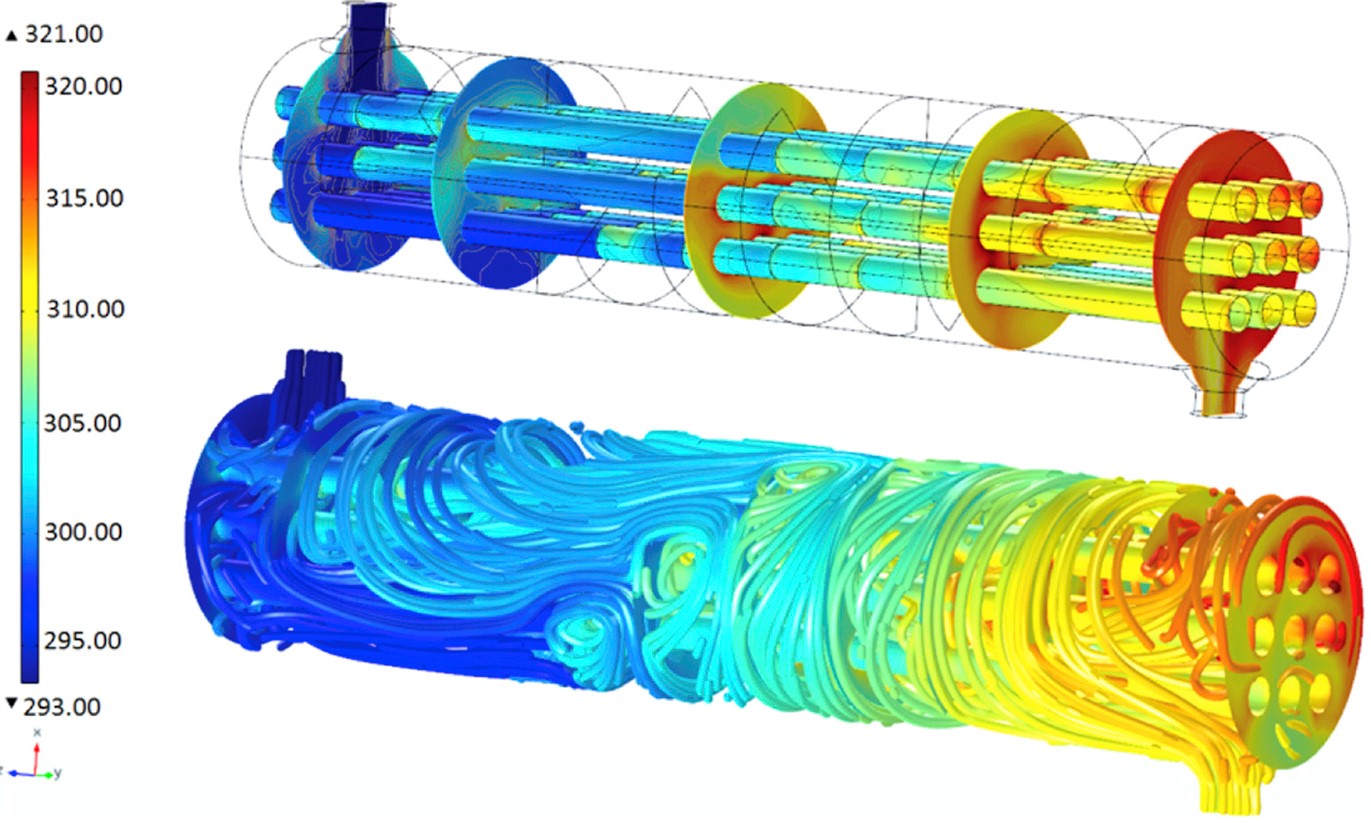
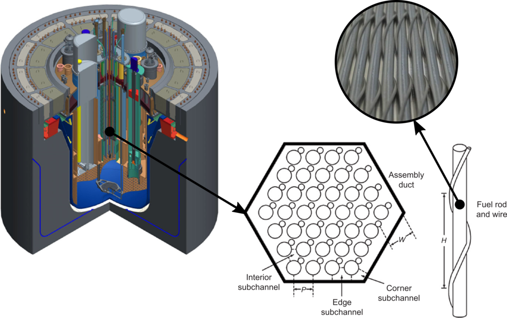
Tube array geometries are often encountered in heat exchangers and nuclear reactor cores. Wrapping a wire helicoidally around the tubes helps preserving the distance between the rods, but also acts as an augmentation device for heat transfer. This is of interest for both the designers of heat exchangers and those of nuclear fuel assemblies.
The use of wires has some implications for the flow-field and the dynamics of the rod array. The cross-flow increases as the wire forces the flow to swirl, which increases mixing but simultaneously the forces acting on the rods. Consequently the rods tend to deform during operation, potentially resulting in unexpected behavior compared to the predictions from the design table. Especially because the fuel rods of this types are often very slender and only clamped at one side.
Meshing takes a big part of the total time to do numerical research. In the case of a wire-wrapped bundle, large difficulties are encountered making the process even more cumbersome. The overset/Chimera meshing technique shortens this process tremendously and makes it more straightforward, potentially even automatic. How it works is schematically visualized in Figure 1, were it is applied to the blade of a wind turbine by a researcher of our group. It uses overlapping grids called “background” mesh and “component” mesh, each computing a solution in the “solve” cells and exchanging information from the “donor” cells to the “acceptor” cells by interpolation.
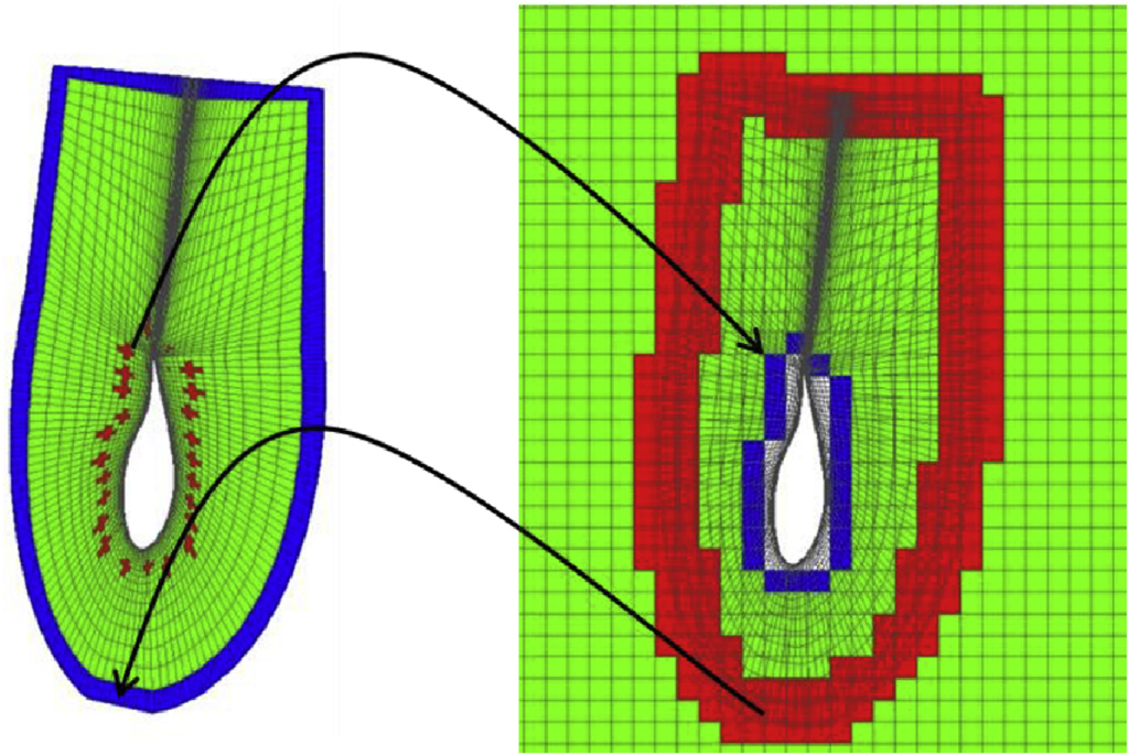
Figure 1: Mesh connectivity technique: (left) component mesh, (right) background and component mesh overlapped. Solve cells are marked in green, donor cells in red and acceptor cells in blue.
The overset technique was extensively used in the late 80’s and 90’s as the design of the Space Shuttle (see Figure 2) was re-examined after the fatal flight of the Challenger in 1986. It successfully contributed to the improvement of the design.
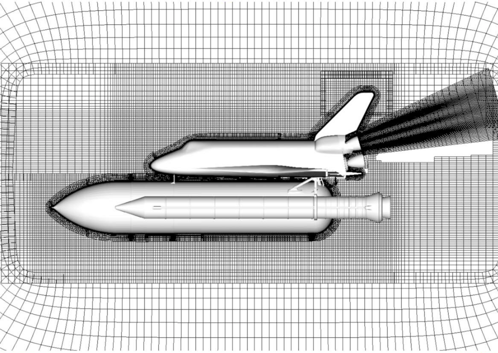
Figure 2: Mesh of space shuttle in which the Chimera technique is applied.
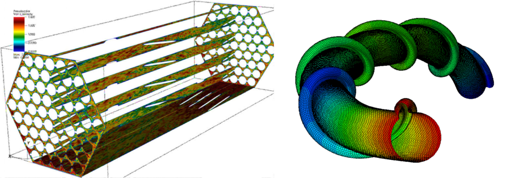
In a previous thesis the overset meshing technique was successfully used on a wire-wrapped tube geometry, both on a single-rod and a bundle. For the single-rod a fluid-structure interaction (FSI) simulation was performed, predicting the flow-induced vibrations and steady deformation of the rod. CFD-simulations were performed on a 7-pin and 19-pin bundle, the results agreeing very well with literature.
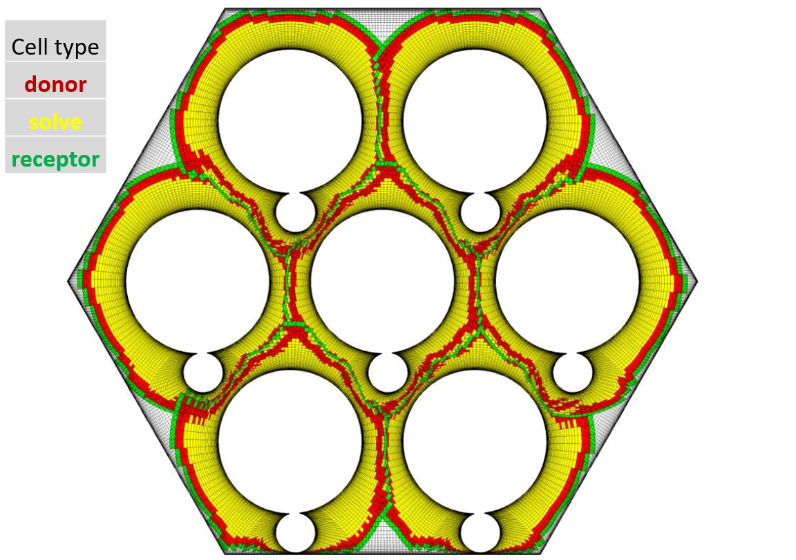
Figure 3: Overset mesh of a 7-pin wire-wrapped bundle.
Another advantage overset meshes offer, besides their great flexibility, is that they can deal better with contacting surfaces. When the fuel pins deform, they tend to contact each other as was shown with simulations of our research group. With classical meshes the CFD solver cannot handle this, but for overset meshes some measures exist that deal with this. This thesis builds upon previous work, but further exploring this contact ability. Another point of interest is the heat transfer from within the fuel pins to the coolant flow. These kind of simulations have always been done on rigid geometries, not taking into account the deformation. A research question of interest here is how much different the heat transfer characteristic becomes when taking this into account. It could be the case that for a deformed bundle higher temperature or more hotspots are predicted, which has a direct consequence for the safety of the reactor.